
In the last few years the importance of High Pressure coolant in machining of complex materials like duplex stainless steels, age hardened super alloys, Inconel, other Heat Resistant Super Alloys (HRSA), titanium etc has grown exponentially: Machining has moved away from the conventional concept of having just a sharp cutting edge to machine such materials and accept a relatively shorter life, to, controlling the chip form and keeping the cutting zone cool, to ensure the security of the cutting edge on a prolonged basis.
This has led many cutting tool manufacturers to offer Toolholders on turning centers with internal coolant with nozzles etc that are directed to the cutting edge.
The concept of using High Pressure coolant directed at the cutting edge with great velocity was developed by some European universities( like the German University of Aachen) who observed great benefits in the machining of difficult to machine materials like titanium and heat resistant super alloys (HRSA);
Let us look at the machining characteristics of these materials to understand why the above concept is having such a great impact in the economical machining of these materials with a high degree of process security.
HRSA materials typically have poor thermal conductivity and hence are prone to work hardening resulting in high cutting forces and high temperatures at the cutting edge that tend to destroy the cutting edge prematurely. Titanium too has similar machining characteristics, but in addition can chemically react with the tool material at these high temperatures.
Conventionally this was handled by:
- A sharp cutting edge having a high positive rake.
- A grade with a high hot hardness (low Co%) and high edge toughness (fine grained)
But conventional solutions gave poor results in the machining of aerospace materials and there was a need to optimize chip flow despite the work hardening tendencies of these materials.
High pressure coolant can provide the following benefits especially in challenging workpiece materials :
- higher machining security.
- consistent machining process.
- fewer machine stoppages.
- better component quality.
- shorter machining times.
We now examine the concept behind this theory and whether it is just:
- High Pressure coolant or high Velocity coolant
- Directed coolant or flood coolant.
- The coiling of the chip into acceptable curls with the help of an optimum directed coolant at an optimum velocity.
In machining of HRSA materials, Duplex stainless steels, titanium the use of cutting fluid directed below the chip at high velocity is vital for lifting and coiling the chip into smaller spirals that help chip evacuation.
High-pressure (HP) cutting fluid -well directed, at high velocity has proven its potential to improve the machinability of difficult-to-cut materials.
Normal Coolant Flow:
Figure 1 shows the conventional application of coolant on a CNC machine.
Just flooding the machining zone with coolant is not enough anymore. If coolants are to be applied effectively, they need to be applied through high pressure jets that are directed correctly. Such a jet, when controlled in a laminar flow, shortens the contact length between chip and rake face. In this form, coolants can affect how the generated heat is distributed and removed, the amount of tool wear generated, how chips are formed and broken as well as the amount of smearing of workpiece mate-rial on the cutting edge. This becomes especially important when machining demanding materials, where heat- and chip control need extra measures.
High pressure coolant when directed below the chip reduces the chip contact on the Tool edge drastically- called the Coolant wedge effect… see fig 2 & 3 below:
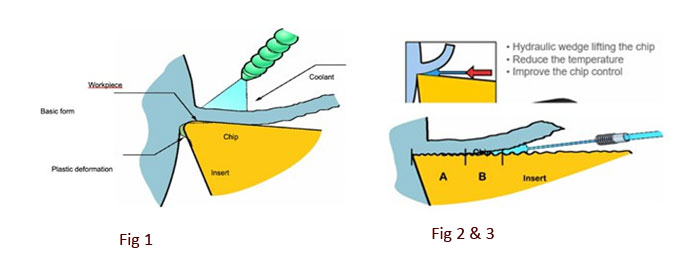
How Does The Coolant Wedge Help?
A high velocity jet of coolant creates a hydraulic wedge between the top surface of the insert and the underside of the chip.
The coolant jet provides localized cooling of the insert in the contact zone (A)
Forces the chip away from the insert face quickly, reducing wear on the insert (B)
Helps to break the chip into smaller pieces and evacuate it from the cutting area.
How Is The Coolant Velocity Created?
Lamellar Flow
In the Tool you need an optimized nozzle to create a parallel lamellar jet of high velocity and which is directed at the cutting zone on top of the insert face and below the chip.
There is a proven theory (Bernoulli) that expresses the relationship between pressure, velocity and flow rate of a fluid, such as a coolant.
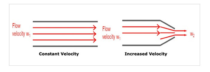
As the fluid passes from a larger-diameter tube to a tube that is smaller in diameter, the flow rate requirements are smaller to achieve a high-velocity jet – the effect of putting a nozzle on the end of a garden hose. The larger the nozzle outlet diameter, the greater the flow rate requirement needed to deliver a certain pressure.
High pressure coolant is more than pressure, it is coolant flow rate and coolant outlet size in the system, from pump to tool.
Thus, the principle behind the application of high-pressure coolant is that a reduction in the fluid outlet (nozzle on toolholder) produces an increase in the fluid velocity coming out of the nozzle. The larger the nozzle, the higher the flow rate of the fluid has to be in the tube and vice versa. Moreover, the number of nozzles (accumulated outlet area) will affect the resulting fluid outlet pressure. (The nozzle efficiency and fluid density are also factors). See pics 4 & 5 above. To achieve the optimum velocity, it is necessary for the machine tool to have a coolant system which can operate at 50 to 80 kg/cm2.
In turning, the nozzle size recommended to produce precision coolant jet with laminar flow and high velocity has a 1 mm bore.
A flow rate of at least 20 litres per minute is recommended.
Exchangeable nozzles with outlet holes are available between 0.6 to 1.4 mm.
The coolant pressure recommended for optimum turning, milling and drilling, for high performance and results in most workpiece materials is @ 50 to 80 bar.
For each 1 mm nozzle being employed in the tool, a coolant flowrate of 5 litres per minute is required to maintain pressure. The variation in nozzle-outlet size should be used to maximize the pressure and utilize the available flow rate.
In milling, using multi-insert tooling, a higher flow rate is required in relation to the number of nozzles in use.
Flow requirement can be reduced by using nozzles with smaller outlet holes. (1 mm diameter nozzle holes for up to ten outlets, 0.8 mm for ten to twenty outlets and 0.6 mm for more than twenty.
In drilling, the flow is as important as the pressure to ensure good chip evacuation through the flutes. High pressure helps to ensure good flow and therefore a secure drilling process. Coolant-hole sizes are optimized to the drill diameter and pump capability to maximize coolant flow. A relatively high flow rate is required to evacuate chips out efficiently through flutes.
As a thumb rule for drills smaller than 12 mm, 16 litres per minute is sufficient. For drills 12 to 40 mm, 30 litres per minute can be good starting values.
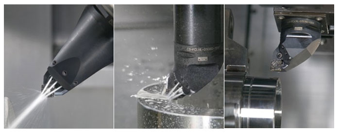
Examples Of Using This Principle In Different Machines Is Shown Below
With High Pressure coolant directed at high velocity as above we can expect:
at the same cutting data: + 50% increase in tool life cutting speed can be increased 20% (50 to 60m/min)